Repairing Harman Kardon Soundsticks III
By Will Thong, Tue 01 December 2020, in category Electronics
By Will Thong, Tue 01 December 2020, in category Electronics
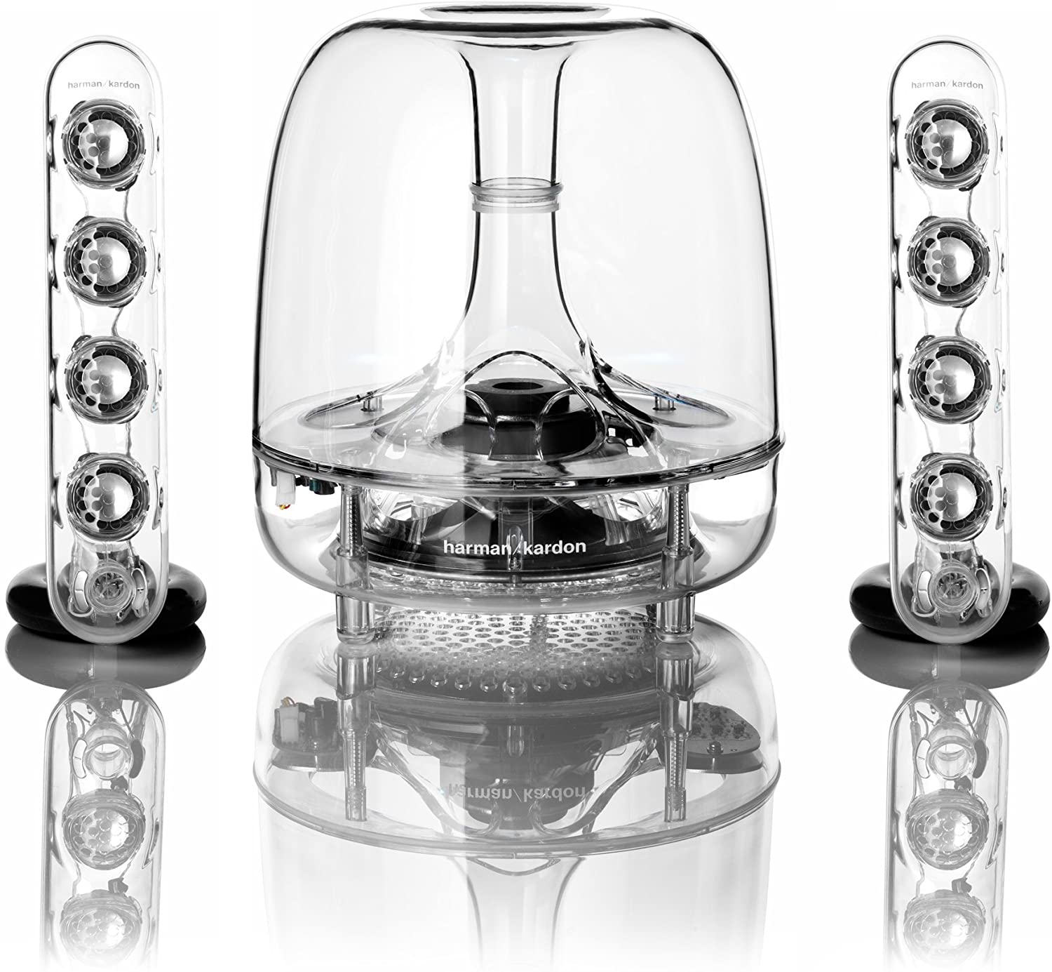
Through cackhandedness, I snapped off one of the pins on the right speaker connector of my Harman Kardon Soundsticks III (non Bluetooth version). I’ve owned these speakers since 2015, so it would’ve been a pretty good innings if I’d thrown them away and bought some new speakers, or I could’ve paid £72 for a replacement right speaker, but I figured I’d try to repair them instead to save some cash. I’d never touched a soldering iron before, but figured it couldn’t be that difficult. This was a mistaken presumption.
There wasn’t much information on how one could go about resoldering the connector, and Harman Kardon used Mini-DIN-4 connectors, for which there is no standard wiring layout, to connect the speakers to the subwoofer (which is where the signal from a source is routed through). They may have chosen to do this rather than just using an RCA jack like they do for the left speaker because this speaker also houses the capacitive volume buttons, but it would’ve been consumer-friendly for them to publish some instructions to help anyone wanting to perform a repair.
I found this helpful blogpost from Nick Brook, who had successfully repaired his Soundsticks II. Although the model was different, my Soundsticks also had a Mini-DIN-4 connector, and upon snipping the wire open at the broken connector, it appeared that a similar 4-wire configuration had been used: a white wire, two grey wires (one light, one dark), a translucent/shiny wire, with some bare, thin wire surrounding the grey wires.
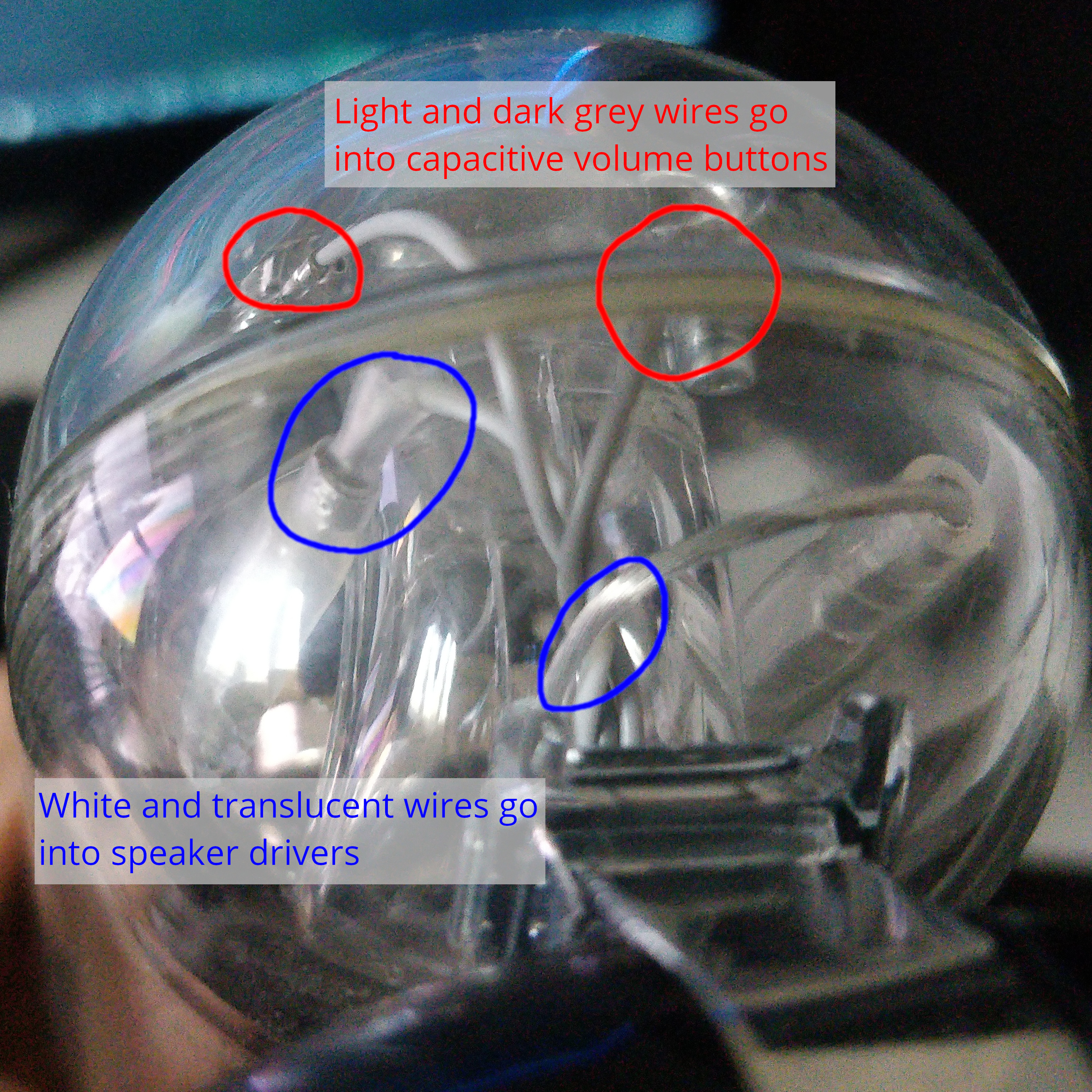
So I bought a Mini-DIN-4 connector for £3 off eBay and followed Nick’s pinout to connect the wire to with help from this incredible 1980s soldering tutorial. However, I got a bit confused and put the translucent wire where Nick had put the shield wire. Turns out this was coincidentally a good mistake to make, as it appears that, looking inside the speaker, Harman Kardon have directed the white and translucent wires up into the speaker drivers.
To my surprise, the speakers worked! But there was a weird clipping sound at higher volumes, and the volume buttons were reversed. I could only conclude that Harman Kardon had entirely unnecessarily changed their proprietary design, presumably just to confuse anyone trying to fix their own speakers rather than buying a new pair.
Three Mini-DIN-4 connectors later (I’m really not very good at soldering and kept melting the plastic), I concluded that there are three crucial differences between the Soundsticks II and III:
I worked out this final point as I had a hunch that the speaker wires might be the wrong way round, and confirmed it with this polarity checker app on my phone. When I played sound into the speakers using Nick’s Soundsticks II pinout using the app towards the phone’s microphone, it indicated that the polarity was incorrect.
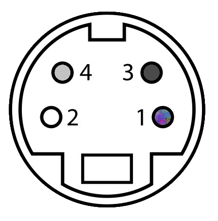
So I think this pinout will yield success if you are trying to repair your own Soundsticks III right speaker. Note that I took the bare wire strands among the sheathed wires and wrapped them around the base of the sheathed wires so they made contact with the metal plug before screwing on the connector’s boot; I found the volume controls were a little temperamental if I didn’t do this, so I think it helps with grounding. Also, the pinout shows the arrangement of the coloured wires as you look towards the connector’s pins, so will need to be reversed along the vertical axis when soldering wires from the solder terminal side. The weird multicolour is an attempt to represent the translucent/shiny wire.
Thanks to Nick for his help!